What is "latency" ?
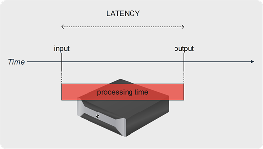
In the engineering domain, the term of latency generally describes the notion of time delay between the input of a system and its response, between a cause and its consequence.
In the communication and IT domain, the latency represents the delay occurring in the transport of information.
For instance, in the context of live TV coverage, it can represent the delay between a live action and the moment it is displayed on the watcher’s screen.
Closer looking at video processing equipment in the production chain, the latency generally represents the processing time elapsed between the instant a video frame enters the system, and the moment it is output.
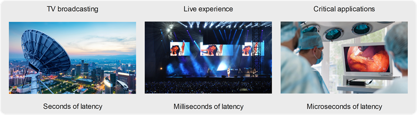
Requirements in terms of latency largely vary with applications’ purpose and with their context of execution.
As an example, TV broadcasting to the final subscribers usually measures latency counted in seconds, while it is counted in frames (dozens of milliseconds) when dealing with a giant screen installed in a soccer stadium or a live event hall. Latency requirements can be expressed in units below the millisecond in industrial, computer vision, and medical applications.
How to measure latency?
First of all, it is important to specify what to measure.
We formerly defined the latency as the processing delay of a video equipment. Actually, this delay is a combination of a capture latency, a processing latency, and a playout latency.
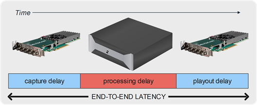
As the DELTACAST products implement the capture and playout interfaces of the video equipment, while the processing part depends on the final application, our measures focus on these video transport steps and assume that the processing part is instantaneous. We hence measure the DELTACAST device contribution to the final product end-to-end latency.
How we measure this contribution is illustrated in the following figure:
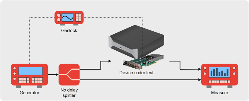
In this test setup, a video generator emits a source signal which goes through a zero-delay splitter producing two identical outputs.
One of these signals is directly connected to the measuring equipment, while the second signal goes through the device under test before reaching the measuring device.
Inside of the device under test, an application captures video frames or smaller portions of video content from a DELTACAST input channel, and forwards them as soon as possible to a DELTACAST output channel.
To provide figures that are meaningful for applications in the TV broadcast domain, the transmitters of the video source generator and the device under test can be genlocked onto a common source. This output signal synchronization influences the end-to-end latency of the device under test, as the emitted video frames are locked to the reference frame rate, hence delayed if they were available sooner.
Frame-based versus sub-frame approaches
The DELTACAST products historically implement a frame-based behavior. The VideoMaster API and its concept of slots also deal with frame granularity.
This is an evident approach for most of the use cases in which DELTACAST cards and FLEX modules are used: media servers, video encoders, video processors, subtitling engines, multiviewers, video servers, all these applications capture, process, timestamp, encode, analyze video frames.
Besides this semantic consideration, these products also rely on architectures, toolsets, and graphic engines that also work on a frame-by-frame basis.
Working on video frames is the default method and the most usual way of processing video content. On the other hand, video frames are not transported atomically and instantaneously on video interfaces like SDI, HDMI, and IP.
All these transport technologies serialize the content on the cable, line after line, pixel after pixel, resulting in the frame spending its complete time slot within the frame rate to be sent on the transport medium:
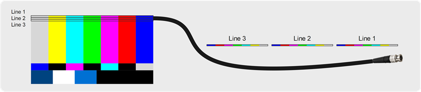
As an example, a 1080p60 video means that 60 frames are emitted each second. Otherwise expressed, one frame is emitted every 60th of a second, so every 16.66667 milliseconds.
Video transport being serialized, this means that a device receives the last pixel of the frame 16.66667 milliseconds after the time it received the first frame pixel.
For systems working on entire frames, this means that the complete frame acquisition prior to processing results in a minimal latency of one frame. Similarly, the emission on the cable of one frame made available by the system will also last for one frame.
Besides video transport layers, most applications also require internal buffering, also counted in a number of entire frames.
Frame-based systems often present an end-to-end latency of several frames, and this delay can be annoying in some use cases. Think about lip-sync problems. About a live concert where the audience could notice the delay between a band live performance and its display on an on-stage giant screen. Think about video feedback equipment during a surgery operation.
Because the end-to-end latency really matters in certain specific cases, it is sometimes interesting – yet more complex and challenging – to work on a sub-frame basis.
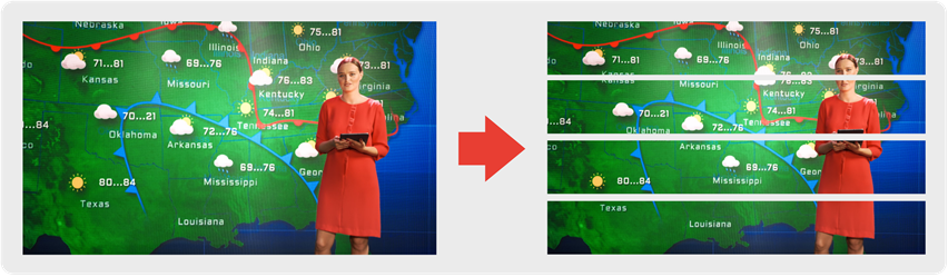
A sub-frame approach means that the video processing is designed to work on a portion of the frames, as soon as they are available.
Let’s imagine a video frame subdivision into four slices. The video being serialized and transmitted pixel by pixel, would mean that an application capable of working on such portions of frames can cut down the latency by a factor of 4.
DELTACAST support both the frame-based and the sub-frame methods. Let’s detail them.
Details on the frame-based video interfacing
DELTACAST video interface cards and FLEX modules implement hardware buffering and software buffering. At both stages, buffers contain entire frames.
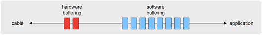
In the case of reception, one complete frame is captured in the hardware memory. As soon as the last pixel of the frame is written into memory, the card issues an interrupt that instructs the driver to start a DMA transfer to move the fame to the host computer memory. As soon as that DMA transfer finishes, the frame is available to the caller application. Thanks to the double-buffering at the hardware level, the next frame is captured by the card while the current frame is DMA-transferred to the host computer.
This framework results in a cable-to-application latency of 1 frame plus the DMA transfer time of that frame:
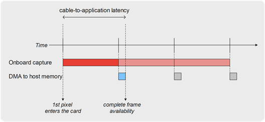
As an example, for a 1080p60 video source reception in 8-bit 4:2:2 YUV, one frame time is 16.7 msec, and the DMA transfer takes around 3 msec on a PCIe Gen2 x4 card (~1500MB/sec) or around 1.5 msec on a PCIe Gen2 x8 card (~3000MB/sec).
The resulting minimal cable-to-application latency is hence around 18.2 msec in a single channel use case. It increases in multi-channel use cases as the PCIe bandwidth is shared amongst all concurrent channels.
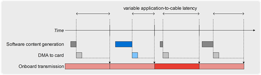
In the case of transmission, the concept of latency does not make sense in every case, because the video frames generation is not necessarily linked/locked to their transmission. Actually, in most cases the output channel starts and frame ticks are asynchronous with the software transmission loop.
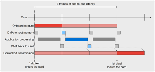
For video processing applications performing some on-the-fly task onto a video feed, the end-to-end latency is a measure making complete sense. The very minimal achievable latency, in this case, is 2 frames, as illustrated by the following figure:
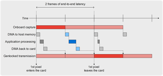
If the video alignment differs a bit, or if the application processing time lasts for a bit longer, or if DMA transfers are a bit slower or delayed due to multi-channel operation, then the minimal latency can quickly increase to 3 frames:
Details on the sub-frame working mode
While all the DELTACAST I/O boards and FLEX modules implement a frame-based API, some of them also implement a sub-frame API. We call this mode Ultimate Low Latency (ULL).
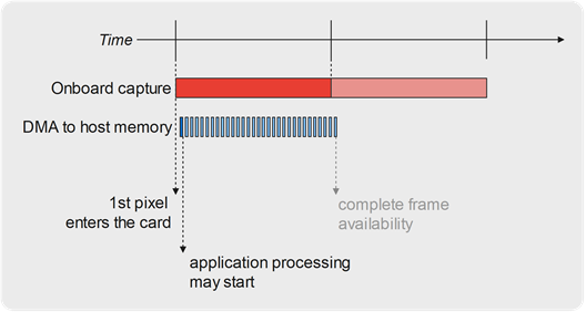
On reception channels, the sub-frame mode allows the application to access the frame buffer while it is still being filled in by DMA from the underlying hardware card buffer. The application can poll the frame buffer filling to known which portion of the frame is ready for processing.
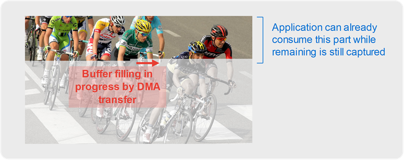
This buffer filling polling method allows a very small reduction of the capture latency, as the DMA transfer runs concurrently with the frame onboard capture. Actually, when the complete frame is captured at the DELTACAST card level, most of it is already transferred to the host computer buffer, and only the last pixels need to be sent by DMA.
The real gain in latency is made if the application is able to start processing the pixels as soon as a few are received, instead of when the complete frame is received like in frame mode.
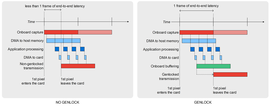
That gain in latency makes complete sense when implementing a video processor realizing some task on a captured live video feed before emitting back the processed signal. In this case, if the application is able to perform its processing on a portion of frames during the capture, then the end-to-end latency can be cut down to one frame when the output is genlocked with the input, and even less in the non-genlocked use case.
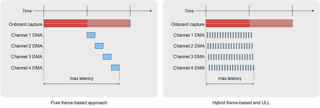
Improving frame mode performances thanks to ULL
As an intermediate solution, activating the ULL mode onboard and still working on a frame-by-frame basis at the application level unlocks important improvements in terms of capture and transmission latency in multichannel use cases.
To illustrate in the case of video reception, one particularity of the ULL mode is that DMA transfer to the host computer memory runs in parallel of frame reception on the card, while in the traditional frame-based approach the DMA transfer is launched once the frame is completely captured onboard reception.
The gain in terms of delay of availability of the complete frame at the application level is quite small in single-channel use cases – around 2 milliseconds for a HD frame, depending on the board generation and on the platform performances.
However, in multichannel and in most demanding use cases near to the PCIe throughput limits, the gain in latency can be huge!
Actually, in this case as the DMA transfers of the different channels are executed sequentially in the traditional frame-based approach, for demanding formats like UHD the frame captured on the last channel of the chain may be transferred quite late, leaving few time for the application to process it within the frame time slot.
When ULL is activated, all the channels operate DMA transfer in parallel of the onboard capture, so that all frames are available to the application nearly at the same time and do not create anymore such a difference between a “first” channel and a “last channel”.
ULL, a new way of thinking frame buffer processing
Besides a drastic reduction of the minimal end-to-end latency, the new ULL mode and its sub-frame approach allow reshaping the way video processing applications are implemented.
Instead of implementing frame-based processing, applications can work on smaller portions of the video frame buffer – from a few slices down to granularity as small as a few lines or a few tens of microseconds.
Through this new mode, VideoMaster even allows handling the processing more dynamically. As an example, imagine processing jobs driven by CPU availability, instead of overprovisioning the system in terms of CPU power, to be sure to be able to process entire frames when they are available.
How Ultimate can the low latency be ?
Working on smaller and smaller portions of frames requires an increasing reactivity at the software level and can become a real challenge. Sub-frame content availability signaling also introduces an overhead and some CPU consumption.
The DELTACAST engineers conducted a series of labs tests to define the finest achievable granularity in reception and in transmission.
Here are our finding:
The RX case
As explained on this technology page, sub-frame accesses allow sub-frame processing at the application level. That basically means that the reception loop interlaces data chunks capture and processing.
The processing time needed depends on the application purpose and on the processing technology ; it also depends on the size of data chunks – larger data needs a longer processing time.
For our experimentations to be realistic, we simulated a 10 microseconds processing time per chunk. Then, we observed how the achievable chunk size varies with the amount of channels running in parallel.
For that we used our DELTA-12G-e-h 2i1c, which is a 12-channels I/O board. All the 12 channels can operate in 3G-SDI and support up to 1080p60, and 3 of the channels support up to 12G-SDI line rates and up to 2160p60 formats. That explains while our tests are bounded to 12 HD channels and to 3 UHD channels.
In this case, the granularity we reached was highly depending on whether the application only processes the active video, or if it also requires ancillary data (ANC) to be captured, as shown in the following graphs.
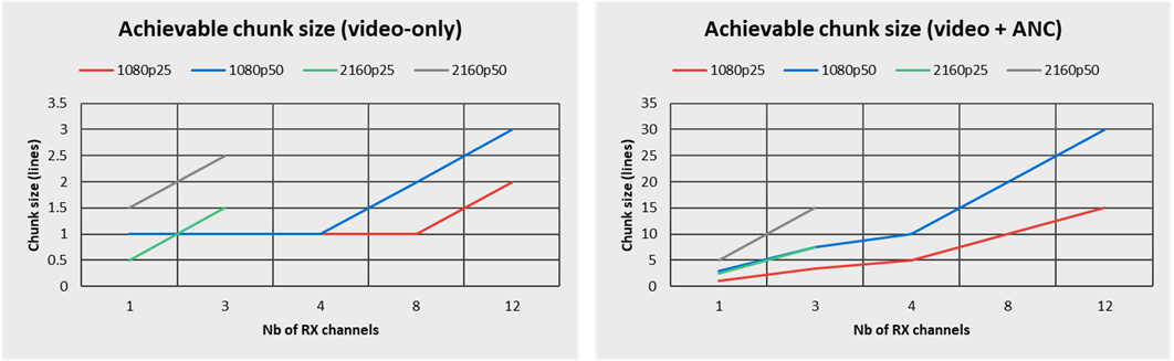
On the left side, we observe that in single-channel, video-only, HD reception use cases, the Ultimate Low Latency working mode allows sustaining a granularity as low as one single video line! Raising the density to 12 parallel channels, the granularity remains around 3 video lines.
On the right side, we see that ANC data processing has an important influence on the achievable chunk granularity, which sizes from 1 to 5 lines in single channel up to 30 lines in a 12-channels test.
Then, we also verified how the application processing time needs influences the achievable granularity, and simulated processing times of 10, 30, 100 and 500 microseconds per slot. Here are the results for 12 parallel capture channels in 1080p50 :
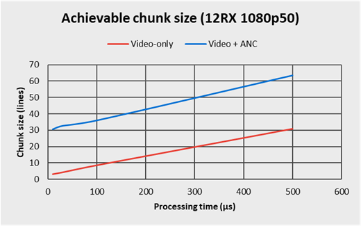
As the graph highlights it, the achievable chunk size linearly varies with the application needs in terms of processing, and the influence of the VideoMaster implementation is negligible.
The TX case
On transmission channels, we found out that the CPU consumption of the Ultimate Low Latency directly depends on the sub-frame access granularity, and is pretty independent from the amount of parallel channels and from the video format.
As a consequence, defining the finest achievable sub-frame granularity depends on how much of the frame duration is needed by the application to perform its own processing, and how much of the frame time can be assigned to the ULL subsystem itself.
The graph below illustrates how the ULL CPU usage evolves with the chunk size in the case of a reasonably loaded system – 4 transmission channels running in 1080p – and with a frame duration of 20 milliseconds.
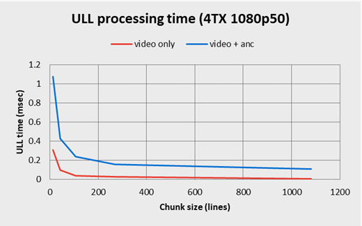
As one can see, the proportion of slot time to dedicate to the ULL implementation raises exponentially as the chunk size gets smaller.
The highest displayed value on the graph for the video-only use case is for a 15-line chunk size. In this case, the ULL implementation requires 0.3 millisecond, letting 19.7 out of the 20 milliseconds of frame duration still available for the application processing.
In the case of video+ANC transmission, the figures are a bit higher and, for a 15-line chunk size, the ULL functions time consumption reach 1.1 millisecond, what means that 18.9 milliseconds can still be dedicated to the application.
The finer the granularity is, the more reactive the system must be. However, for frame subdivisions as low as one single line, one can expect the ULL implementation to request around 5 milliseconds in video-only, and around 15 milliseconds out of the 20 in video+ANC use cases, what becomes tight but still feasible.